Quasi-Linear Convective Systems
What is a Quasi-Linear Convective System?
- First off, QLCS stands for Quasi-Linear Convective System
- What does “Quasi” infer? Quasi is defined to mean “seemingly; apparently but not really”. This is because a QLCS is never going to be 100% linear, but it is close enough that it can be approximated as such
- They are a subclassification of a Mesoscale Convective System (MCS)
- What is a Mesoscale Convective System? As defined by the American Meteorological Society’s Glossary of Meteorology, a MCS is defined as any ensemble of thunderstorms producing a contiguous precipitation area that is on the order of 100 km or greater in horizontal scale in at least one direction
- A group of storms moving in conjunction with one another as a line
- Also commonly referred to as a squall line – In this lesson we will utilize both terms (QLCS and Squall Line), but understand that they both mean the same
How Does an MCS Evolve?
- Mesoscale Convective Systems can evolve from originally isolated convection along an air mass boundary
- The cold pools of the initially isolated convective cells tend to merge, forming a larger, more elongated cold pool that is capable of initiating new cells along the length of the initiating boundary
- This process is referred to as upscale growth of convection
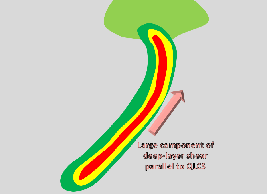
- Heavily reliant upon the orientation of the deep-layer vertical wind shear/environmental system-relative winds in the upper-levels
- When the deep-layer shear/environmental system-relative winds have a large component that is parallel to the initiating boundary, upscale growth is favored
- Conversely, when the deep-layer shear/environmental system-relative winds have a large component that is orthogonal to the initiating boundary, upscale growth may be inhibited
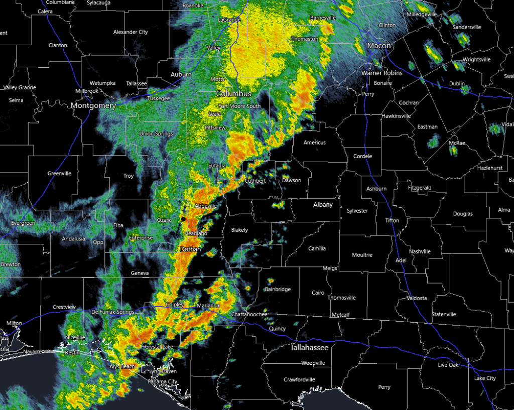
A Quasi-Linear Convective System (QLCS) stretching from Georgia to the Florida Panhandle on March 31st, 2025. Photo courtesy of RadarScope.
Squall Line Development with Respect to Time
- Squall Line Evolution Explanation:
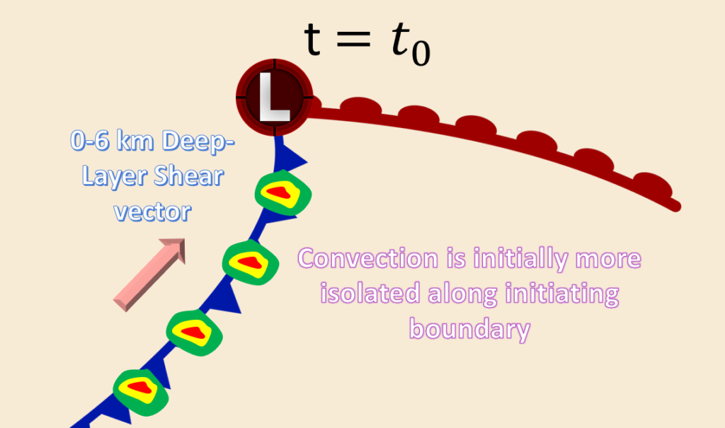
- In the beginning at time $$t={{t}_{0}}$$, convective initiation begins to occur sporadically along the initiating boundary. Where storms form is a function of environmental characteristics such as forcing for upward motion, relative humidity, CAPE, temperature, etc…
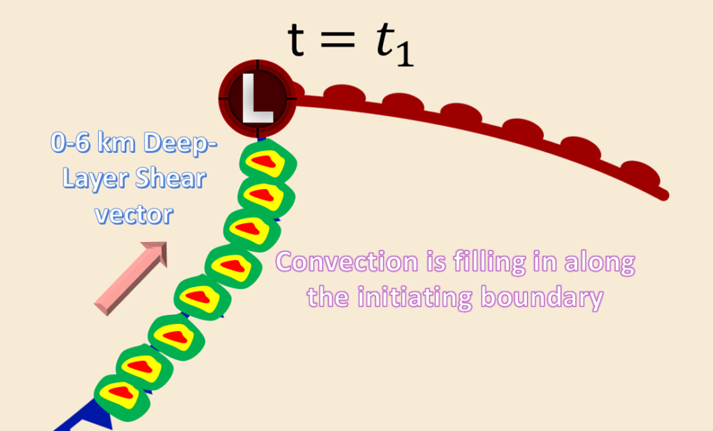
- As time progresses, convection begins to fill in along the initiating boundary. This is likely a result of a strengthening cold pool/greater forcing for upward vertical motion or entering into a more favorable environment.
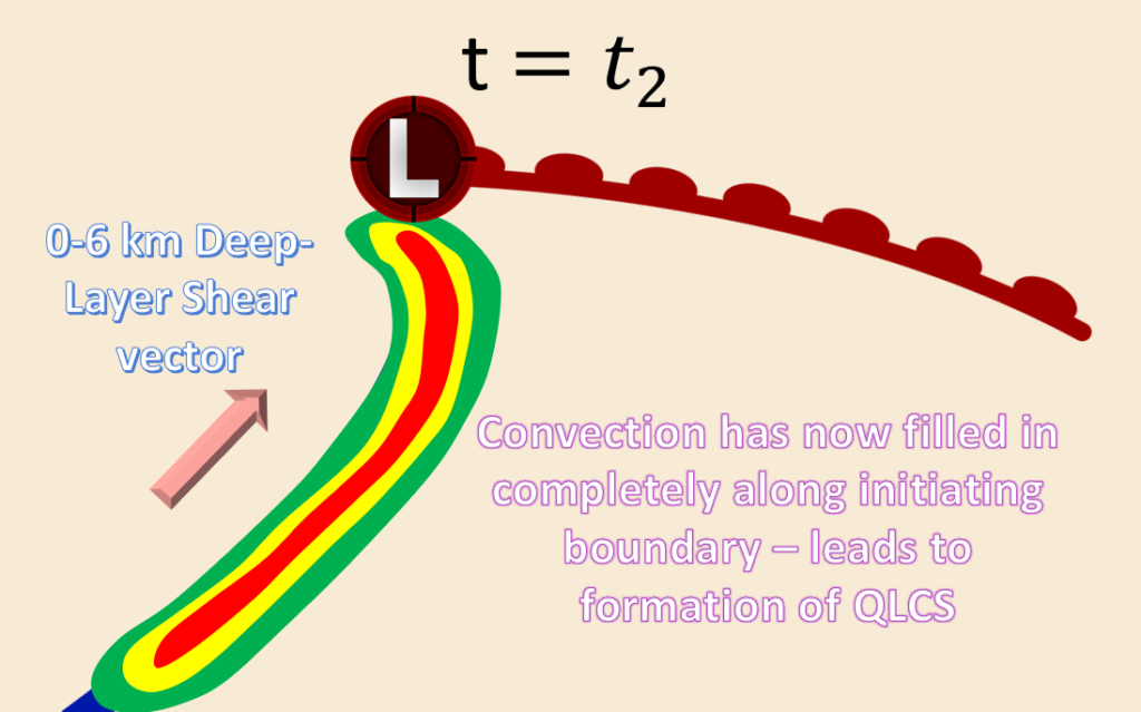
- Lastly, as time progresses even further, convection has now become practically completely filled in along the entirety of the initiating boundary. This leads to the formation of a squall line.
- In other cases:
- MCSs can develop almost immediately after convection initiation (i.e., upscale growth occurs almost immediately after initiation). Why?
- This can be a result of very strong forcing along an air mass boundary in conjunction with an environment characterized by high instability (CAPE) and weakly capped
- Other factors that will be discussed in more advanced lessons could also be in play.
- MCSs can develop almost immediately after convection initiation (i.e., upscale growth occurs almost immediately after initiation). Why?
MCS Classification
- Squall Lines or Quasi-Linear Convective Systems (QLCSs)
- Possess a linear appearance on radar reflectivity
- Bow Echoes
- They possess an arc-shaped or bowing appearance on radar reflectivity
- They are typically embedded within the larger-scale squall line structure
- On occasion, an entire squall line can bow
- Mesoscale Convective Complexes (MCCs)
- Anvil is fairly circular
- Discussed more in-depth in a later lesson
Bow Echo
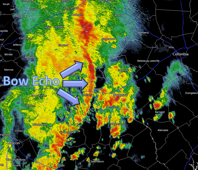
Radar reflectivity showing a bowing line segment associated with a squall line on March 31st, 2025. Photo courtesy of RadarScope.
Line-Echo Wave Pattern (LEWP)

Web page is still under construction, stay tuned for daily updates! Make sure to check out the Single-Cell, Multi-Cell, and Supercell Thunderstorm pages in the meantime!!
Squall Line Structure/Types
- The convective towers and most intense radar reflectivity are typically found along the leading edge of the squall line
- A much broader region of enhanced radar reflectivity associated with the trailing stratiform precipitation region is commonly found to the rear of the system
- The trailing stratiform region is separated from the leading edge by a region of lesser reflectivity often referred to as the transition region
- This type of squall line is typically found within environments characterized by line-normal vertical wind shear that is primarily constrained to the low-levels
- The squall line shown in the diagram here was formed by way of an eastward advancing frontal boundary through an environment containing an abundant amount of atmospheric instability
- Structure varies between the different types of squall lines
- At the low-levels, a squall line tends to appear 2-D as opposed to 3-D
- However, in the mid-levels, squall lines tend to be more three-dimensional
- Whether a squall line is quasi-two-dimensional versus cellular (three-dimensional) depends upon environmental relative humidity (RH)
- Relatively drier air in the low-levels tends to support quasi-two-dimensionality due to stronger cold pool development
- Relatively moist low-level air tends to favor weaker cold pool, and thus leads to a more cellular/three-dimensional structure
- Whether a squall line is quasi-two-dimensional versus cellular (three-dimensional) depends upon environmental relative humidity (RH)
Squall Line Structure
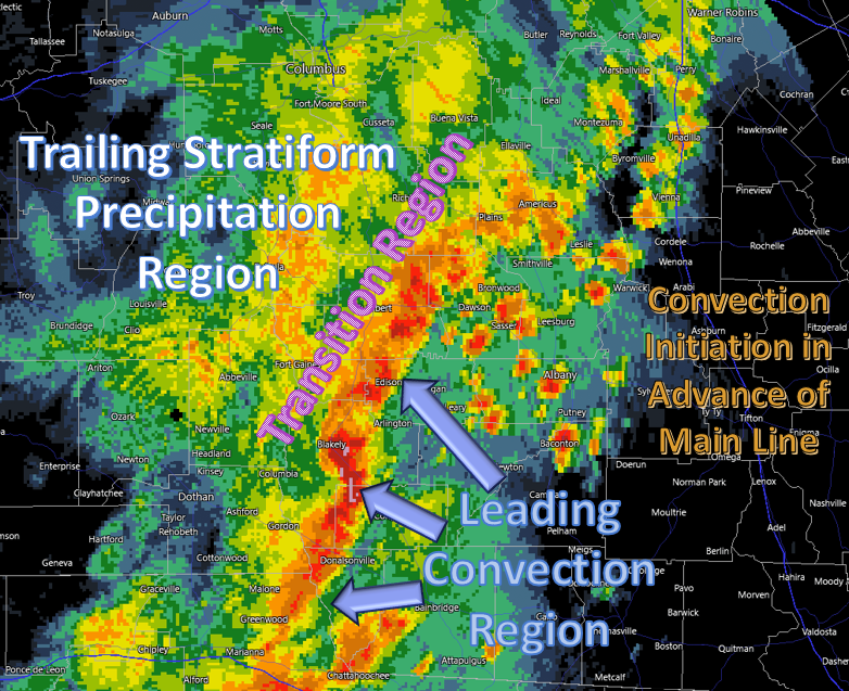
Radar reflectivity depicting a squall line possessing a well-defined leading convection region, a transition region (shown in the area of lower radar reflectivity values), and the trailing stratiform precipitation region. Also shown here is a group of cells resulting from convection initiation out ahead of the main squall line. Photo courtesy of RadarScope.
Trailing Stratiform (TS)
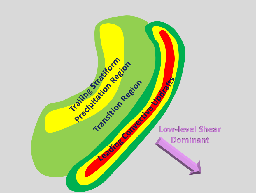
The most common type of squall line. Form within environments dominated by low-level wind shear that is orthogonal to the QLCS. This typically results in front-to-rear facing system-relative winds at all levels within the storm, leading to hydrometeors being deposited to the rear of the system.
Leading Stratiform (LS)
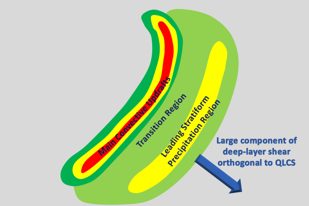
These systems form within environments characterized by a large component of the deep-layer wind shear orthogonal to the system and pointing from the rear to the front. This results in hydrometeors being deposited out ahead of the system.
Parallel Stratiform (PS)
These types of squall lines form when a large component of the deep-layer wind shear is parallel to the system. This results in hydrometeors being deposited parallel to the system.
Squall Line Behavior/Dynamics
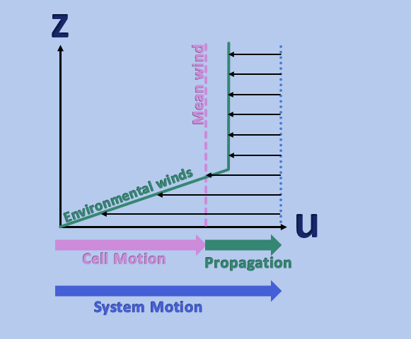
This diagram shows us why squall lines within environments dominated by low-level wind shear tend to favor Trailing Stratiform (TS) Squall Lines. Typically, the cell motion is with the mean wind throughout the depth of the updraft (pink arrow) and the direction of propagation is favored on the down low-level shear flank, hence the propagation vector is pointed in the same direction. The system motion is the summation of the cell motion vector and the propagation vector. Thus, squall lines experience front-to-rear system-relative winds at all levels. Photo adapted from “Mesoscale Meteorology in Midlatitudes” by Markowski and Richardson.
- A squall line that is within an environment characterized by line-normal, rear-to-front, low-level wind shear, hydrometeors will tend to be deposited to the rear of the system
- This is due to the development of a front-to-rear flow through the system
- How it All Works?
- Low-level inflow approaches the squall line via a front-to-rear flow and is subsequently lifted to its LFC by way of the translating gust front – Air parcels retain their front-to-rear momentum as they ascend through the leading updraft
- This flow undergoes gradual ascent to the rear of the main line, producing slight upward vertical motion with vertical velocities on the order of 0.5 m/s, resulting in the trailing stratiform precipitation region that is often observed
- In environments characterized by low-level wind shear, the system-relative winds tend to be front-to-rear at all levels in the squall line. See diagram
How Are Squall Lines Maintained?
- Squall line maintenance requires that the environment is characterized by moderate-to-strong vertical wind shear
- Depending on where the wind shear is constrained within the atmosphere will ultimately determine the squall line structure: Trailing Stratiform (TS), Leading Stratiform (LS), or Parallel Stratiform (PS)
- Squall lines require regions characterized by an abundant amount of atmospheric moisture and instability
- Require a delicate balance between the environmental wind shear and cold pool strength – determines updraft tilt
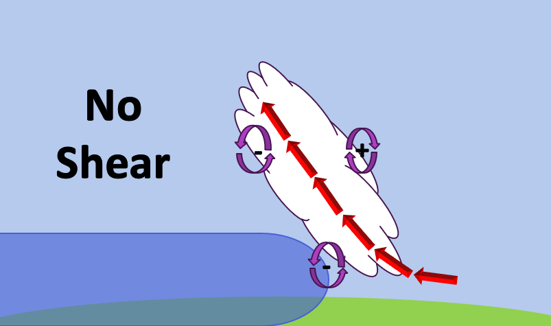
No Shear & No Cold Pool
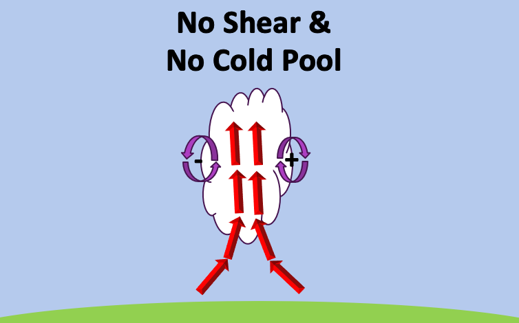
In the absence of BOTH environmental wind shear and a cold pool, the horizontal vorticity generated on the flanks of the updraft can be sufficient for the updraft to remain erect. This is true for the early stages of development before the formation of an evaporatively driven cold pool. The presence of a cold pool, along with the strength will have an effect on the tilt of the updraft.
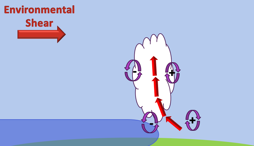
Shear Present & No Cold Pool
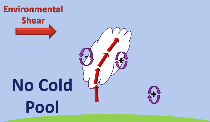
In the presence of shear and no evaporatively driven cold pool, the updraft will tilt downshear. This is a direct result of the horizontal vorticity generated by the environmental wind shear.
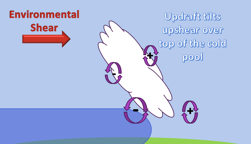
Cold Pool Present & No Shear
In the situation where an evaporatively driven cold pool develops in the absence of environmental wind shear the updraft tends to tilt rearward over top of its cold pool. This is the direct result of the horizontal vorticity imbalance across the updraft.
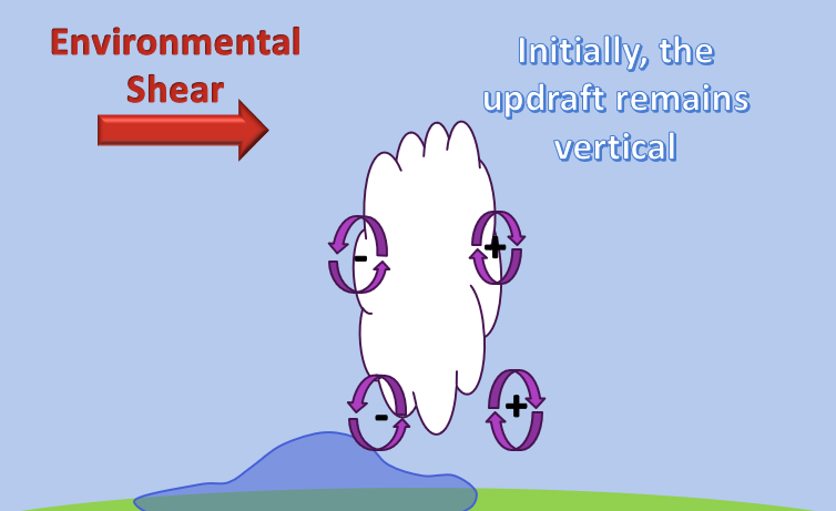
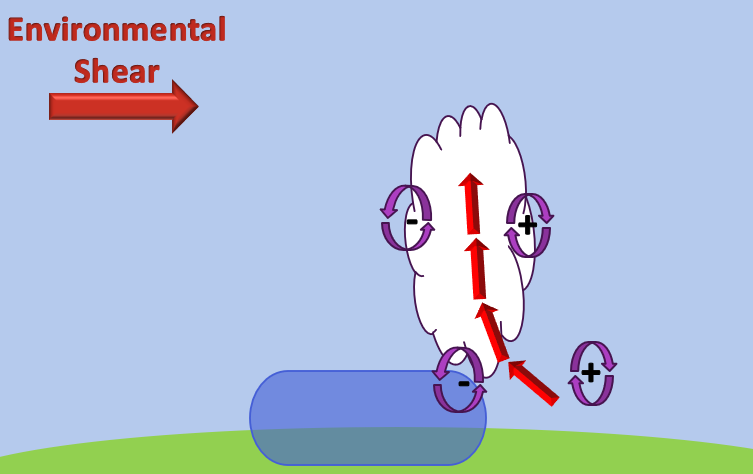
Cold Pool & Shear Present
In the presence of both shear and an evaporatively driven cold pool, if the horizontal vorticity generated by the environmental wind shear is equal and opposite to the horizontal vorticity generated by the cold pool, the updraft can remain erect in the manner demonstrated in the graphic above.
- The majority of what is currently understood regarding squall line maintenance can be accredited to what is referred to as RKW Theory which came about from a study by R. Rotunno, J. Klemp, and M. Weisman
- According to RKW theory, the primary mechanism that is responsible for maintaining a long-lived/healthy squall line comes from the very delicate balance between the horizontal vorticity generated by the low-level environmental wind shear and that generated by the advancing cold pool
- Also, RKW theory suggests that squall line intensity is ultimately dependent upon the updraft tilt
- Tilted Updraft = Greater Entrainment = Weaker Squall Line
- Erect Updraft = Less Entrainment = Stronger Squall Line
- RKW theory suggests that one of the most important aspects for squall line longevity is that the gust front remains erect
- This fact infers that the horizontal vorticity associated with the low-level environmental wind shear is equal and opposite to the horizontal vorticity that is baroclinically generated via the cold pool
- According to “Mesoscale Meteorology in Midlatitudes” by Markowski & Richardson, RKW theory implies an optimal low-level shear of 17.0 – 25.0 m/s – erect gust front updraft
- However, as these squall lines evolve – shear that is initially sufficient early on its life may become insufficient later on
- Severe straight-line winds can occur and do occur in squall lines not possessing an erect updraft
- Many squall lines producing severe weather actually possess an upshear tilt overtop of its cold pool – This leads to the development of a rear inflow jet and bow echoes – commonly responsible for production of severe weather
- Severe straight-line winds are not highly correlated with the strength of the updraft and are actually more related to the speed of the squall line itself
- RKW theory is focused on the gust front updraft – misses the big picture – What about the rest of the updraft that can stretch all of the way up to the tropopause?
- More on this topic will be found in the Advanced Undergraduate Section! Check back later for a direct link once the web page has been completed! There is currently no scheduled release date for that page just yet!
Rear Inflow Jet and the Development of Bow Echoes
- It is crucial to note that in many squall line environments, a rear inflow will develop in the mid-levels
- Generally, the strength of the rear inflow is related to the intensity/tilt of the leading convective towers – Ultimately dependent upon the environmental CAPE and SHEAR
- Furthermore, the rear inflow gradually descends as it approaches the leading edge of the convective line – This descent results in adiabatic warming, which through the Hypsometric Equation, decreases the surface pressure
- This can ultimately result in a wake low that may be observed at the surface to the rear of the mesohigh found within the area characterized by heaviest precipitation/greatest evaporative cooling
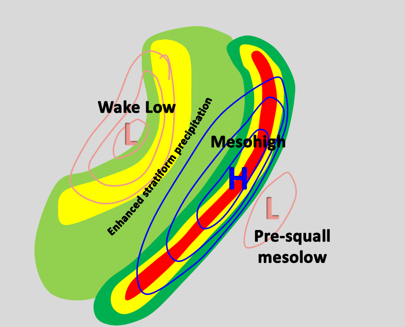
This graphic shows us that in response to the Rear Inflow Jet (RIJ) that descends as it approaches the leading convective line, a wake low often forms to the rear of the system. In conjunction with this, a mesohigh is typically found within the area characterized by the heaviest precipitation/greatest evaporative cooling. Photo adapted from “Mesoscale Meteorology in Midlatitudes” by Markowski and Richardson.
- Squall line updrafts do tend to develop a rearward tilt with time
- This is primarily the result of the strengthening of the cold pool and little/no change in environmental wind shear
- This results in an imbalance between the cold pool generated vorticity and the environmentally generated vorticity
$$t={{t}_{0}}$$
This figure shows that initially, the horizontal vorticity generated by the cold pool and that generated by the environmental wind shear balances one another. This leads to an initially erect updraft.
$$t={{t}_{1}}$$
This figure depicts the same updraft at a later time in its lifecycle with a stronger/faster advancing cold pool. This imbalance between the horizontal vorticity generated by the cold pool and that resulting from the environmental wind shear results in a rearward tilting updraft.
Large CAPE
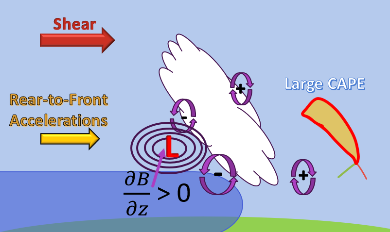
This graphic depicts the case of a strong CAPE environment with a rearward tilted updraft. In this case the pressure minimum above the cold pool is stronger and thus, resulting in a strong RIJ. Photo adapted from “Mesoscale Meteorology in Midlatitudes” by Markowski and Richardson.
- Rear-to-front accelerations develop within a squall line, in response to the upshear tilt of the updraft over top of the cold pool
- A rearward tilted updraft tends to result in a mid-level pressure minimum above the cold pool resulting in the development of the rear-to-front accelerations of air parcels into the rear of the system
- Relatively low pressure is found where: $$p’=-\frac{\partial B}{\partial z}<0$$ meaning, $$\frac{\partial B}{\partial z}>0$$
- This explains the development f the Rear Inflow Jet (RIJ) – However, there are other ways that this phenomenon can be explained
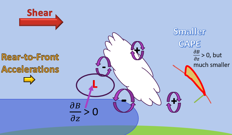
- The strength of the rear inflow increases as CAPE increases
- In the scenario of a lower CAPE environment, the $$\frac{\partial B}{\partial z}$$ term would be smaller, thus resulting in a weaker pressure minimum above the cold pool
This graphic depicts the case of an environment characterized by smaller CAPE along with a rearward tilted updraft. In this case, the pressure minimum above the cold pool is much smaller than the case with large CAPE. Thus, leading to a weaker Rear Inflow Jet as indicated by the smaller rear-to-front acceleration vector. Photo adapted from “Mesoscale Meteorology in Midlatitudes” by Markowski and Richardson.
Small CAPE
- Another way that is utilized to explain the formation of the Rear Inflow Jet (RIJ):
- Vorticity
- The backside of the cold pool acts to induce horizontal vorticity which works to accelerate air up and over the cold pool
- Similarly, once the updraft tilts rearward over top of the cold pool, the rear portion of the updraft works in conjunction with the back end of the cold pool to accelerate air forward towards the leading convective line
- Vorticity
No RIJ
RIJ Present
What is the Importance of the Rear Inflow Jet?
- The rear inflow jet explains how a tilted gust front updraft can re-establish a vertical structure
- The RIJ can result in the formation of a Bow Echo
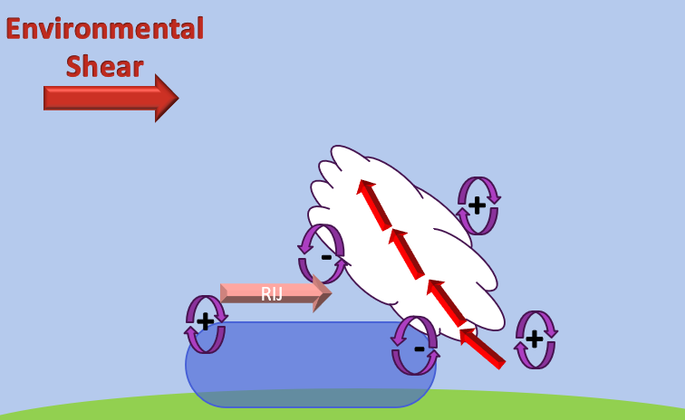
- Counter-rotating vertical vorticity couplets can straddle BOTH ends of a bow echo – bookend vortices
- Formation of Bookend Vortices:
- Form as a direct result of vortex lines being tilted into the vertical by the leading gust front updraft
- These vortex lines are generated via the advancing cold pool and are subsequently tilted into the vertical by way of the leading updrafts – this results in two counter-rotating vorticity couplets
- The tilting of environmental vorticity can actually dominate that generated baroclinically by the cold pool IFF the environment is characterized by strong vertical wind shear
- These bookend vortices act to enhance the RIJ and initiate the bowing process
- At first, both rotating couplets remain of similar strength. After a few hours and by work of the Coriolis Force, the counterclockwise couplet dominates and gives rise to the comma-shaped appearance later on in the lifecycle of the bow echo
- What about Bow Echoes?
- Damaging winds are most often found in the apex of the bowing segment
- Some bow echoes produce severe damaging winds while others do not – we don’t fully understand why!
- Environments tend to be characterized by large CAPE and low-level wind shear
- CAPE can be in excess of 5,000 J/Kg
- 0-2 km shear (and 0-6 km shear) can be as large as 25.0 m/s – sufficient for the production of supercells
- Since bow echo environments and supercell environments are characterized by strong shear (> 20.0 m/s), it makes sense that supercells often undergo upscale growth into squall lines, eventually leading to bow echo formation (especially HP supercells)
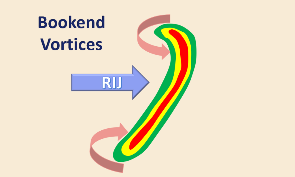
Figure depicts the case of two bookend vortices on either side of a bowing line segment. The northern bookend vortice is rotating counterclockwise whereas the southern one is rotating clockwise. These vortices help to initiate the bowing process.
Shelf Clouds & Lightning
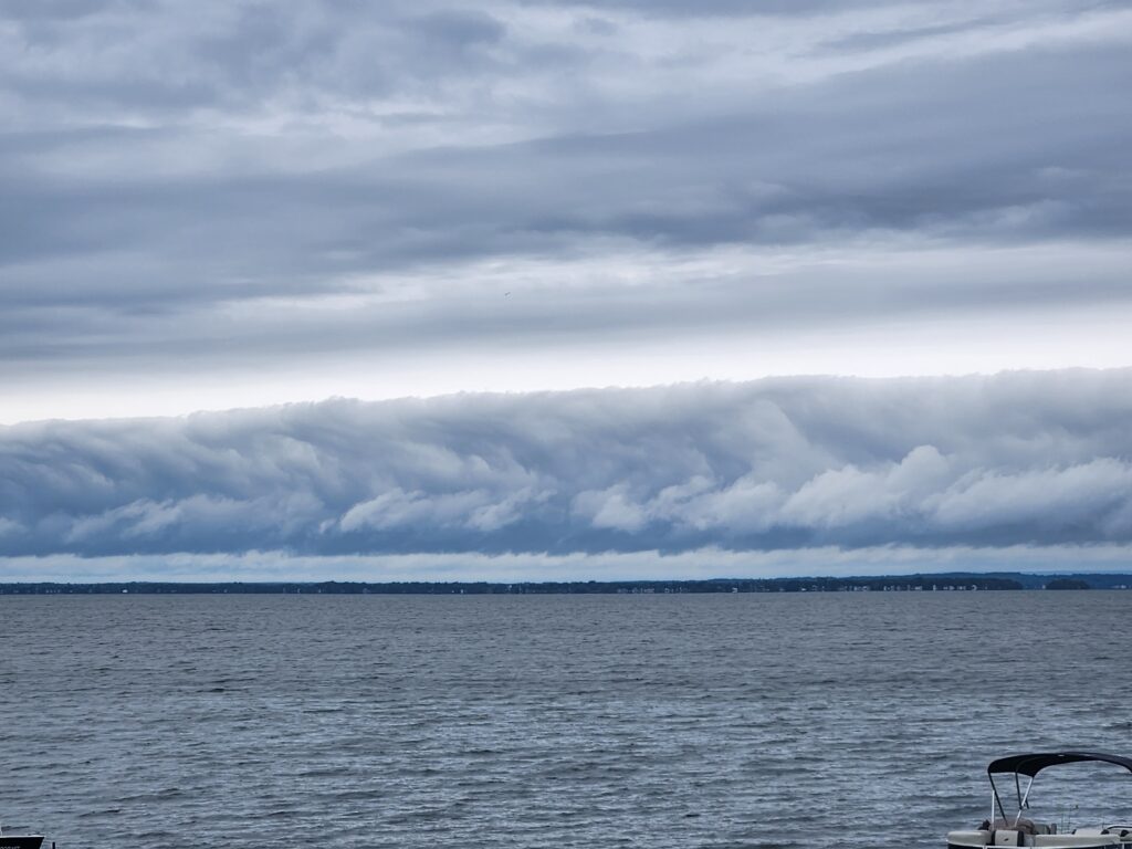
This photo shows a shelf cloud associated with a QLCS moving to the north over Lake Ontario. Many squall lines will be accompanied by a very photogenic shelf cloud such as this one shown above, thanks to the upward vertical motion along the leading edge of the advancing gust front. More will be said about shelf clouds later on!
Some QLCSs/Squall Lines will be accompanied by a LOT of lightning flashes! Take a look at all of the lightning strikes that were associated with a QLCS passing through Central Pennsylvania! Photo courtesy of LightningMaps.org.
Coming Soon!!!
- How do Shelf Clouds form?
- What are Roll Clouds and How do They Form?
- Stay tuned!